Haremos uso del A/D 10 bits, D/A 8 bits del MCU R5F104PJAFB. El micrófono, la bocina y la salida de audífonos con la que cuenta la tarjeta de evaluación YRDKRL78G14. Grabaremos 21,000 muestras del ADC a 10 Khz para posteriormente reproducirlas en el DAC de 8 bits.
- Inicializaremos el módulo ADC Y DAC
- Muestreamos ADC a 10 Khz
- Reproducción del buffer en el DAC a 10 Khz.
DESARROLLO:
- Del manual Renesas RL78G14 RDK User's Manual ubicamos los diferentes pines del micrófono, bocina y conector de audífono:


- Del YRDKRL78G14 schematic se muestra los componentes del circuito de audio:


PASOS:
- · Creación de un proyecto:
2.- New/ C Project

- Configurar proyecto:

2.- Seleccionar C/C++ Build / Settings / Linker / Device y establecer los siguientes parámetros:
OCD = 85
Option Byte = efffe8
Palomear: Use range of debug monitor area. Nota: No establecer ningún valor solo dejarlo en blanco.
Apply y después OK.


3.- Las rutinas de inicialización y muestreo del ADC y el DAC son:
void SR_VOICE_PLAYBACK_INIT(void)
{
LED4_PIN
= 0; // PIN como output
SPK_SHDNn
= 1; // alto
SPK_GAIN = 0; // bajo
AMP_SHDNn = 1; // alto
HEADPH_SDn = 1; // alto
SPK_SHDNn_PIN = 0; // como salida
SPK_GAIN_PIN = 0; // como salida
AMP_SHDNn_PIN = 0; // como salida
HEADPH_SDn_PIN = 0; // como salida
R_ADC_Create(); // inicializa
ADC 10 bits 2.37 us de muestreo
// DAC
DACEN = 1U; /* supply DA clock */
DAM = 0x00;//_00_DA0_CONVERSION_MODE_NORMAL |
_00_DA1_CONVERSION_MODE_NORMAL;
/* Initialize DA0
configuration */
DACS0 = 0x00;//_00_DA0_CONVERSION_VALUE;
/* The reset status of ADPC is analog input, so it's unnecessary to set.
*/
/* Set ANO0 pin */
PM2 |= 0x04U;
/* Initialize DA1 configuration */
DACS1 = 0x00;//_00_DA1_CONVERSION_VALUE;
/* The reset status of ADPC is analog input, so it's unnecessary to set.
*/
/* Set ANO1 pin */
PM2 |= 0x08U;
// START
DACE0 = 1U; /* enable DA0 conversion */ //Audifonos
DACE1 = 1U; /* enable DA1 conversion */ // bocina
// STOP
//DACE1 = 0U; /* stop DA1
conversion */
// DACE0 = 0U; /* stop DA0 conversion */
}
void SR_VOICE_PLAYBACK(void)
{
int index = 0;
unsigned int i, ADC10bits;
ADS
= 0x05;//_05_AD_INPUT_CHANNEL_5;
ADCE
= 1; /* enable AD
comparator */
/* The reference voltage stabilization
wait time (1 μs) */
for (i = 16; i; --i)
__nop();
/* First conversion (result is
undefined)
* (example for software trigger mode and
one-shot conversion mode)
*/
while (index < SAMPLE_SIZE)
{
ADIF = 0;
ADCS = 1;
while (ADIF == 0)
{
__nop();
}
ADC10bits = ADCR >> 8U;
sample[index] =ADC10bits;
index++;
delay_100us(1);
}
LED4 = OFF_;
delay_ms(1000);
for (index = 0; index < SAMPLE_SIZE;
index++)
{
DACS0 = sample[index];
DACS1 = sample[index];
delay_100us(1);
}
}
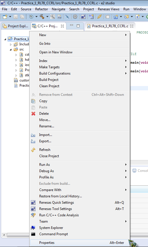
- Agregar código, compilar y debug:
--> Practica #13
2.- Compilar con el icono del martillo, debug con el icono del insecto y correr software:

VÍDEO:

VÍDEO:
No hay comentarios.:
Publicar un comentario